45W IRF510 HF Linear Amp
Boy it’s been a long time between posts. Sorry about that. I got real lazy and just starting pumping my content into twitter and really just never took the time to document things.
Anyway, here is a project I built to get me out of QRP land and being heard my frequently on the 20M and 40M bands.
“CQ CQ CQ”
Finally getting around to sitting for my HAM license I started off with my first HF radio, the very useful uBitX v6. It’s a great radio to start with for a tinker like me. It’s open sourced schematic and firmware allows fiddling and updating and there is always a wealth of ideas and projects on the internet for it.
With it’s mighty 5W output and using my home-brew EFHW antenna I would make countless “CQ” calls hoping someone would hear me. I went on for weeks if not months tweaking this, and tuning that but nobody seemed to ever hear me. So I set about creating my first linear amplifier. Inspired by a design in “Experimental Methods in RF Design” EMRFD I set about building myself a linear amplifier to get above the noise.
“Oh the things you learn”
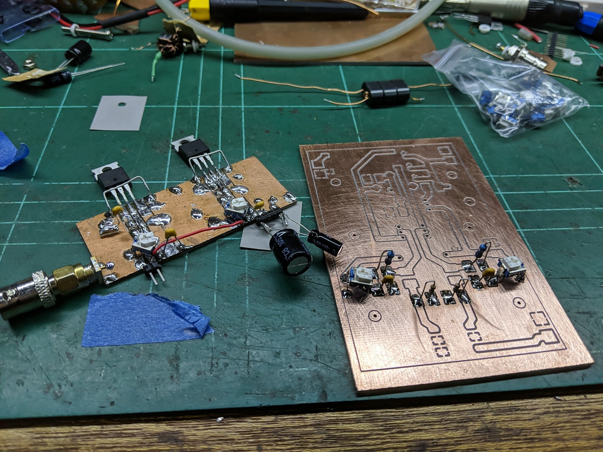
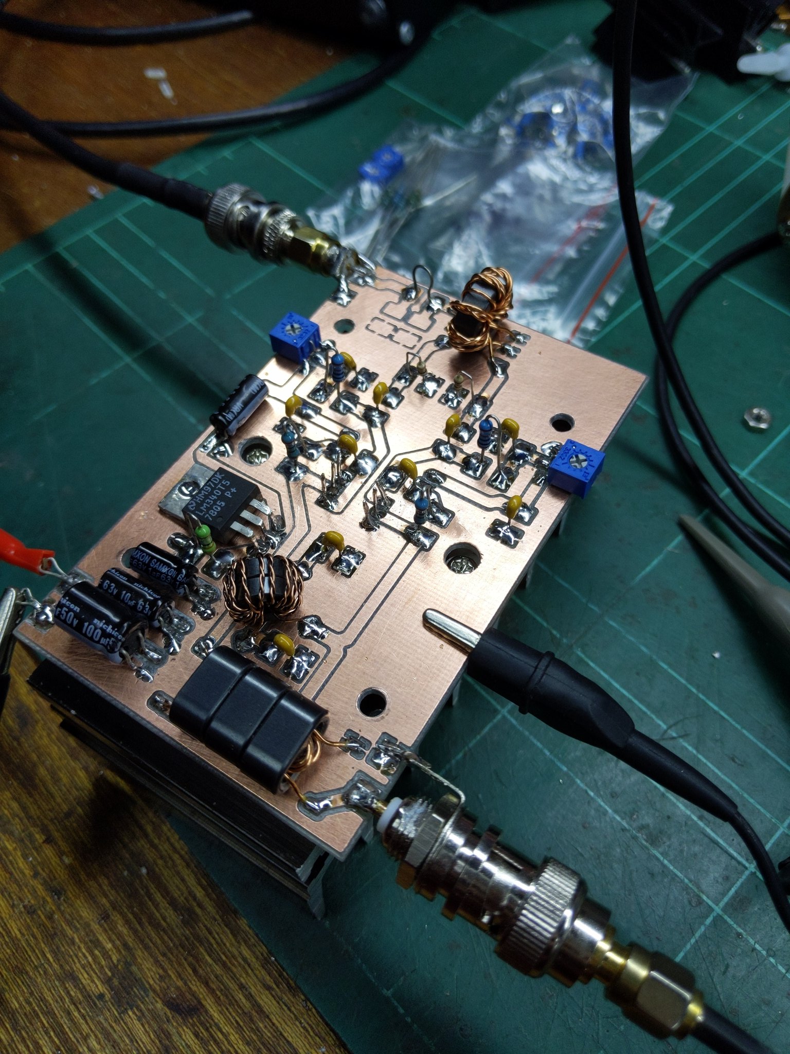
So, I at first figured I’d bash together a prototype on some copper clad and see how it would go…
I got some output! 4dBm (2.5mW) input netted me 31dBm (1.2W) output from 12V!
Suffice to say I was stoked…. then it started oscillating.
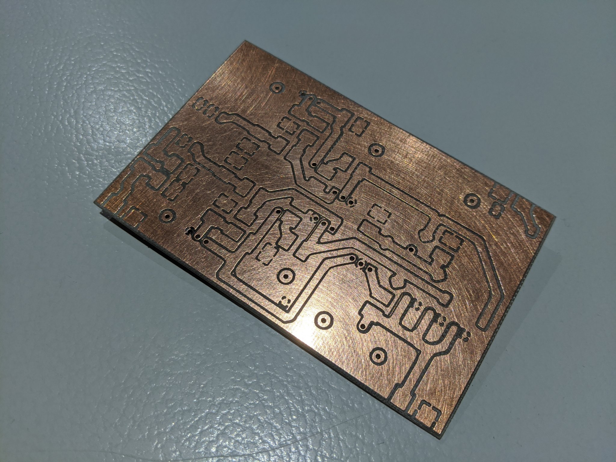
Speaking with my Elmer he suggested my crappy hacked together layout wasn’t conducive to a high power amplifier with fairly high gain, and that perhaps I should do a cleaner layout. So I cracked out my CNC mill and Kicad and made a prototype.
“There ain’t no thang like a CNC”
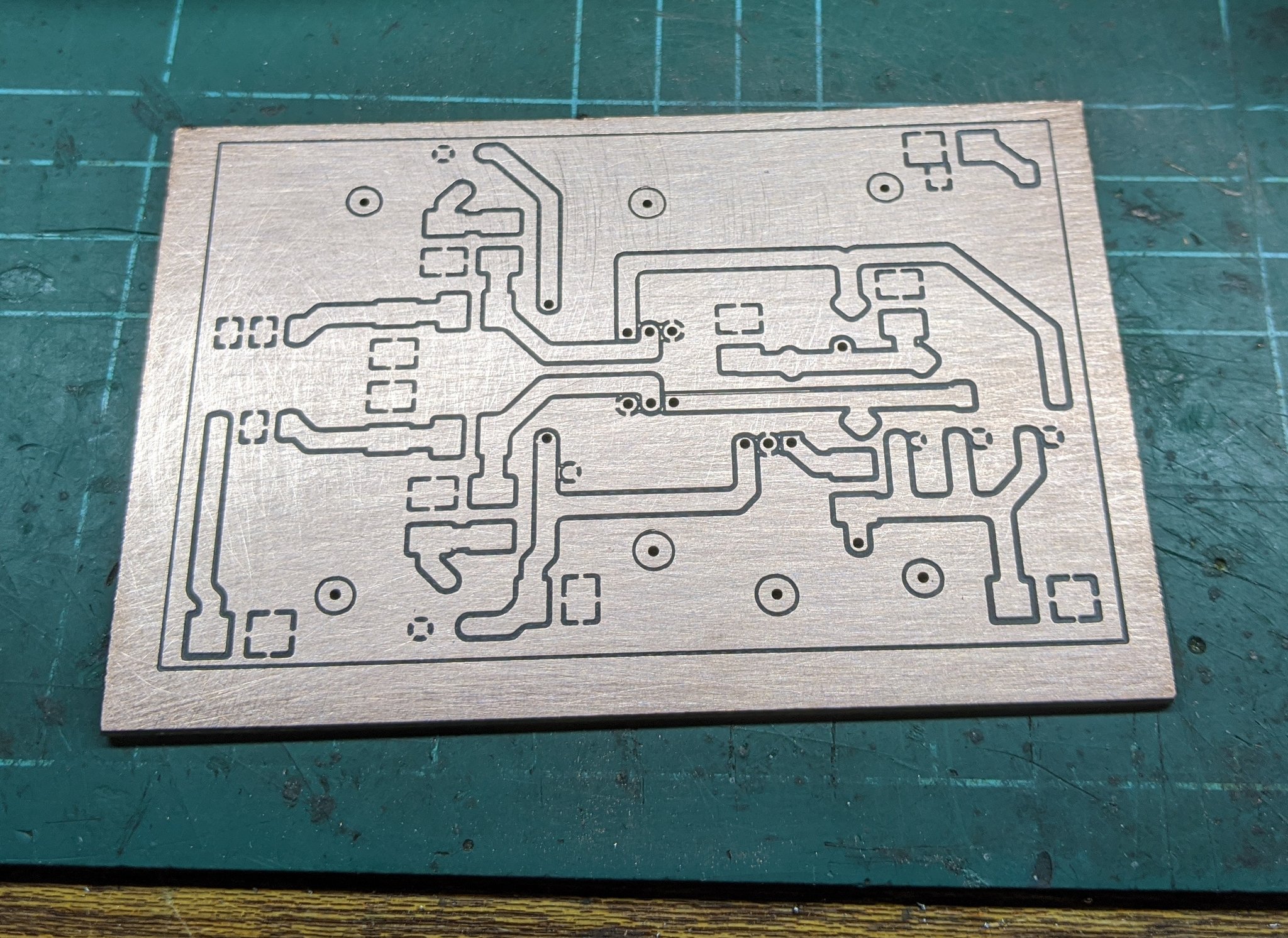
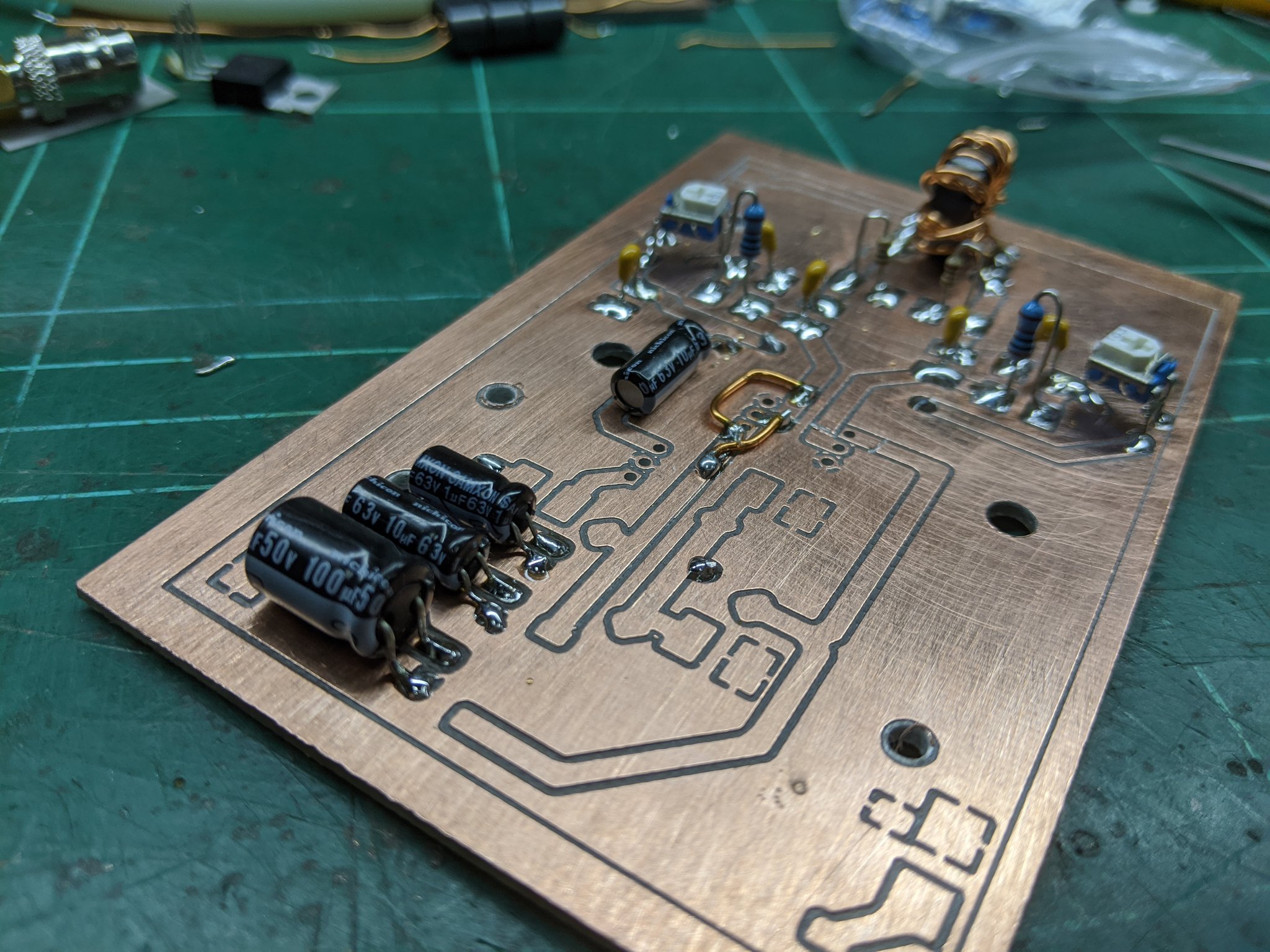
Layout done, board turned out nice. Time to build it.
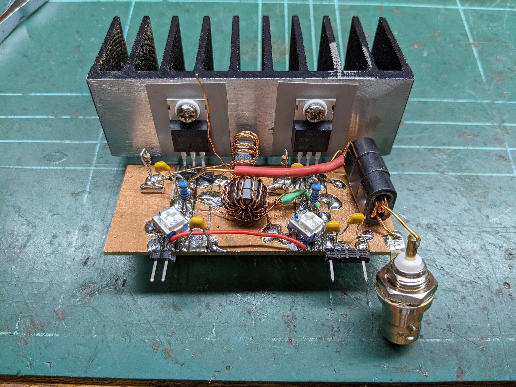
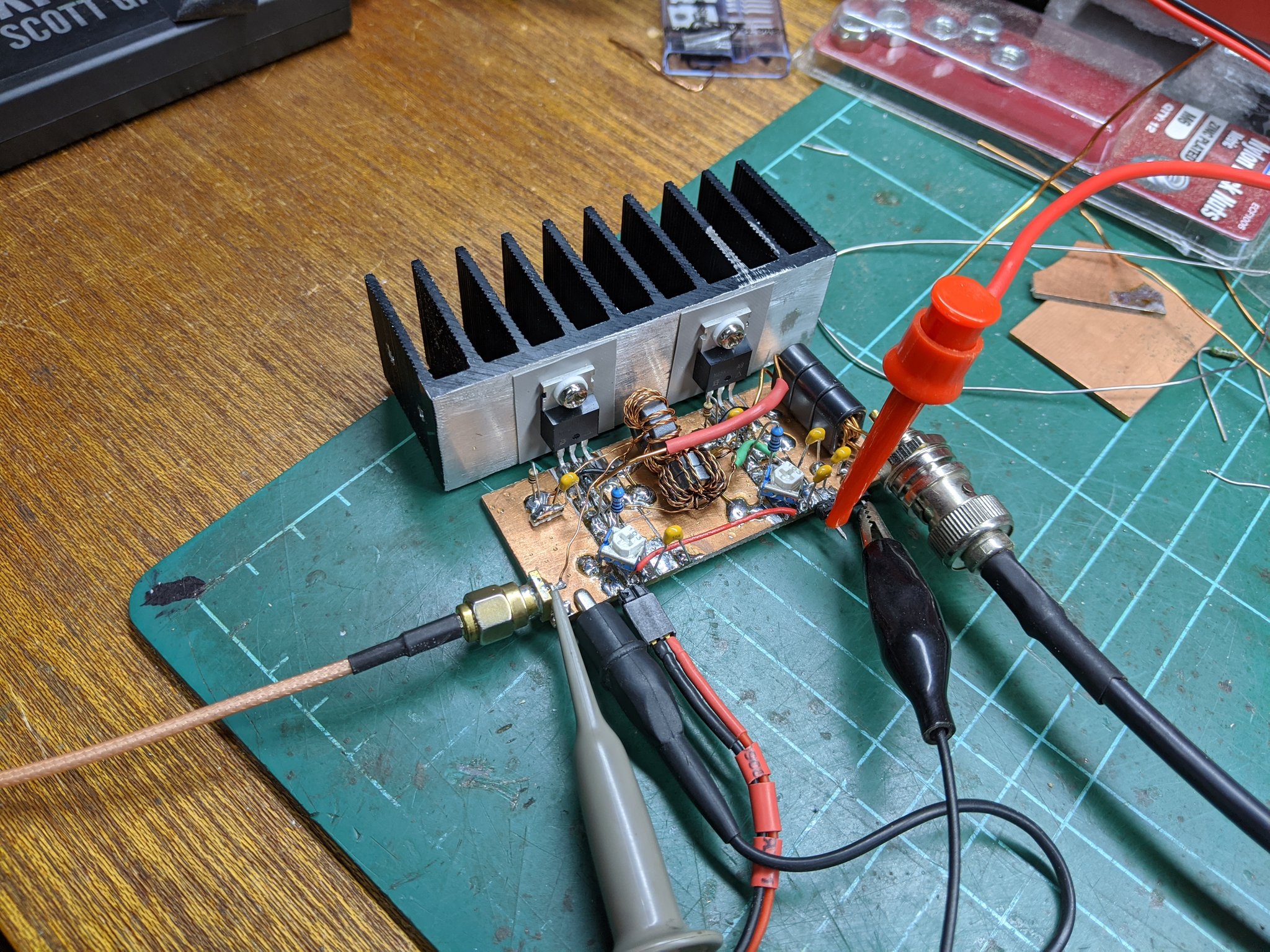
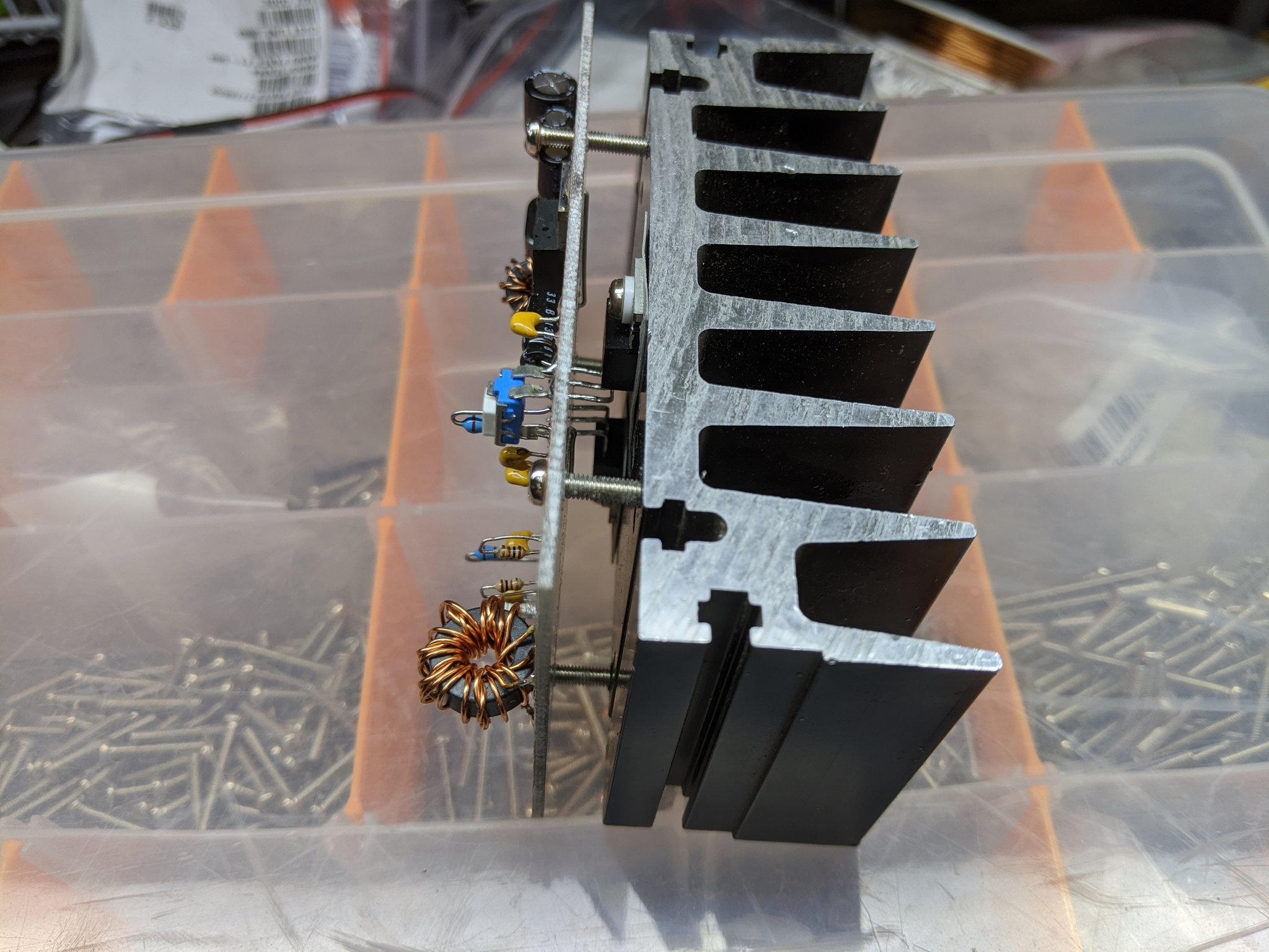
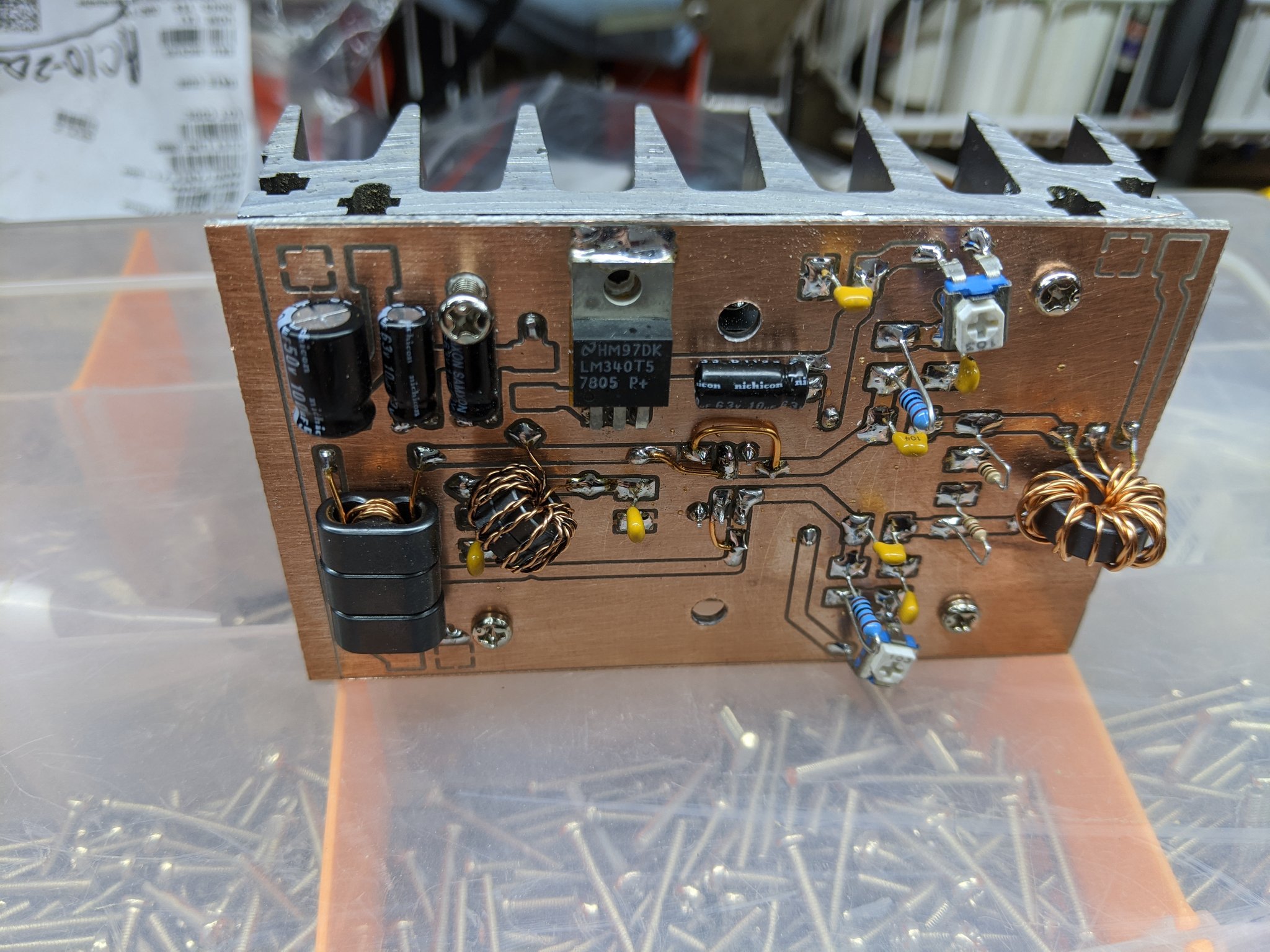
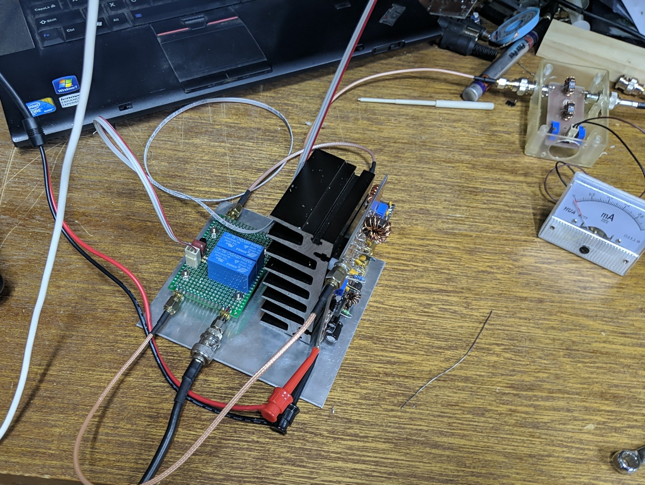
Using a large chunk of heat-sink I cut down from an old stage lighting dimmer, I mounted the MOSFETs with insulators onto the heat-sink. The PCB was then mounted on top and the board mounted on stand-offs.
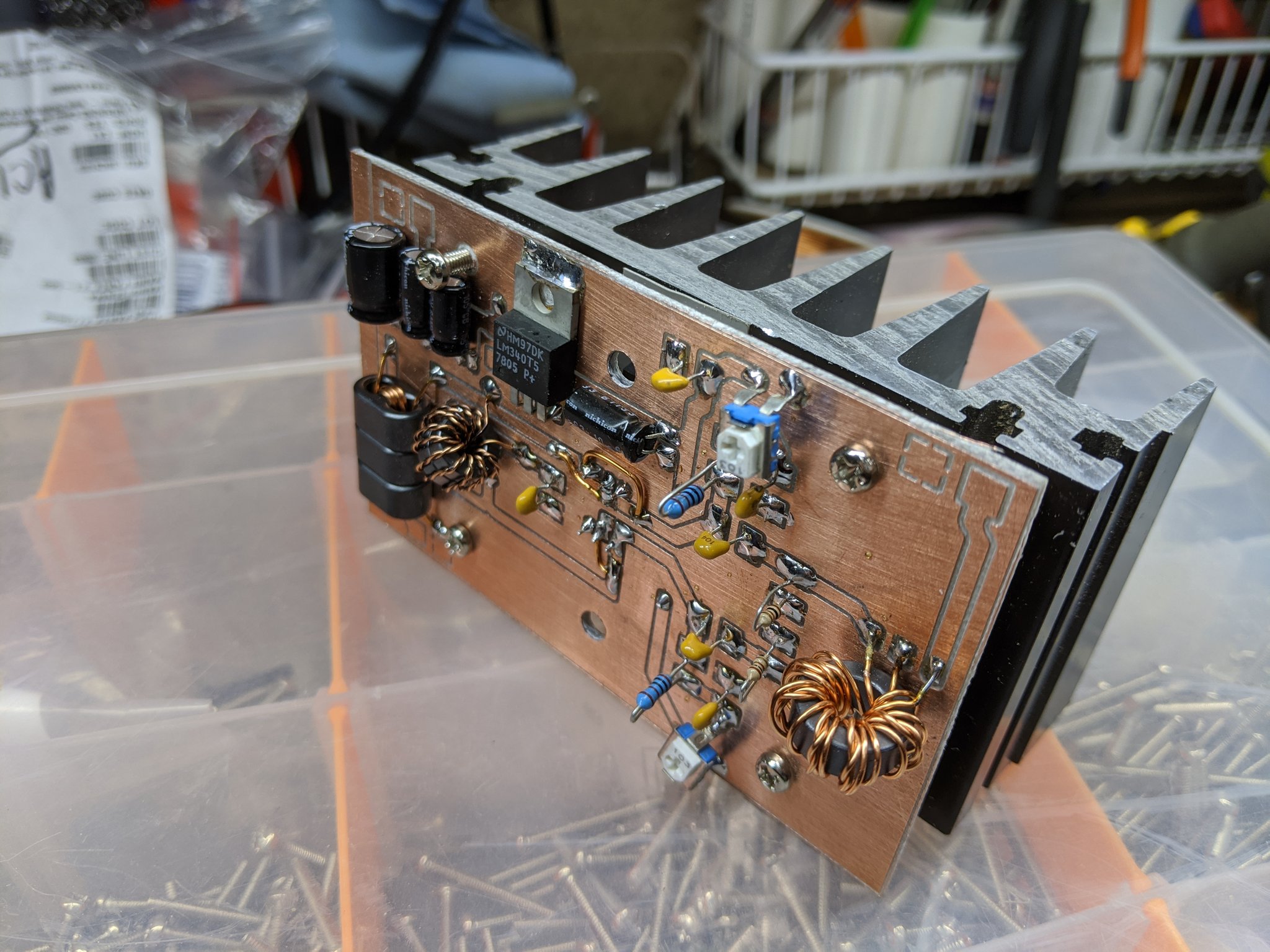
It was about this time I realised I screwed up the schematic and had the gate and drain on one MOSFET arse about. Dutifully I hacked in a modification and continued.
All the components and coils were wound, and the moment of truth
Power up time!
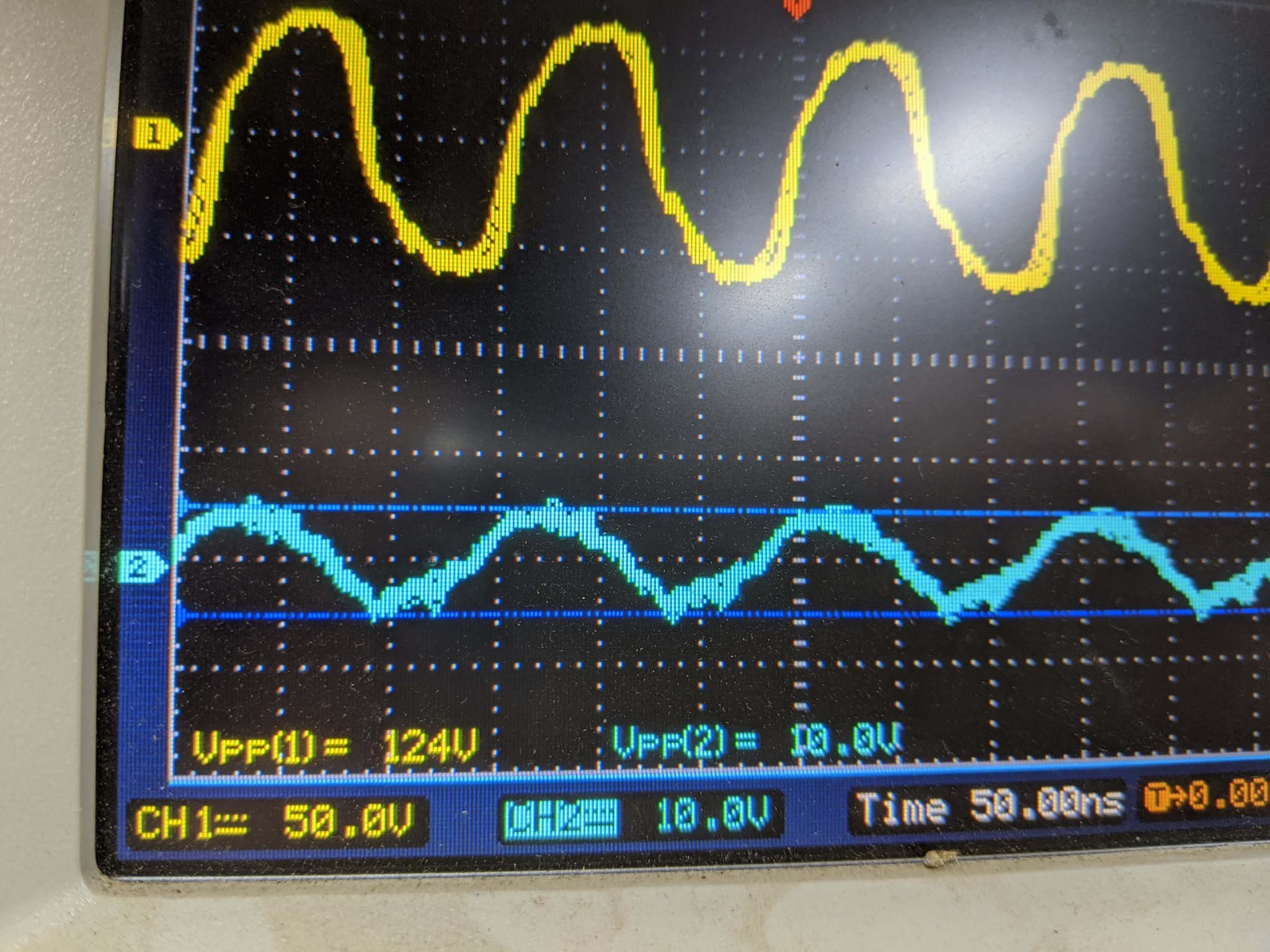
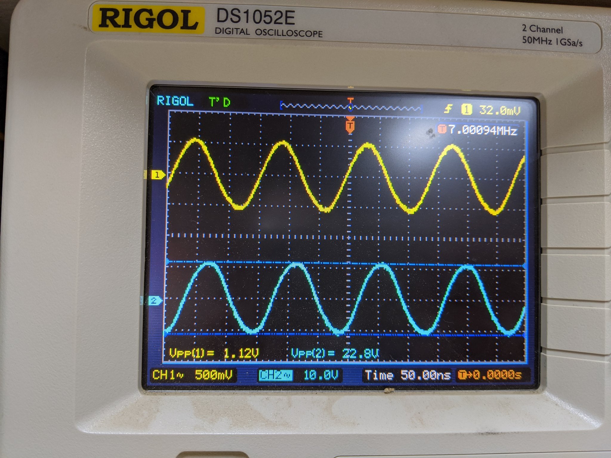
Powered it up, connected it to my uBitX and whistled into the mic and received 46dBm (39.8W) of output from 24dBm (250mW) of input! I was very very pleased. No oscillations, nice clear output and all looked very good and pleasing.
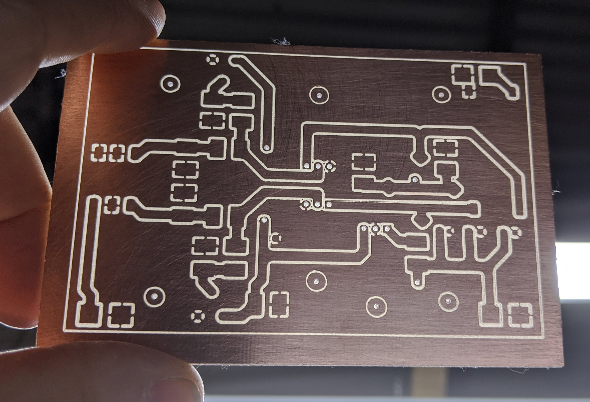
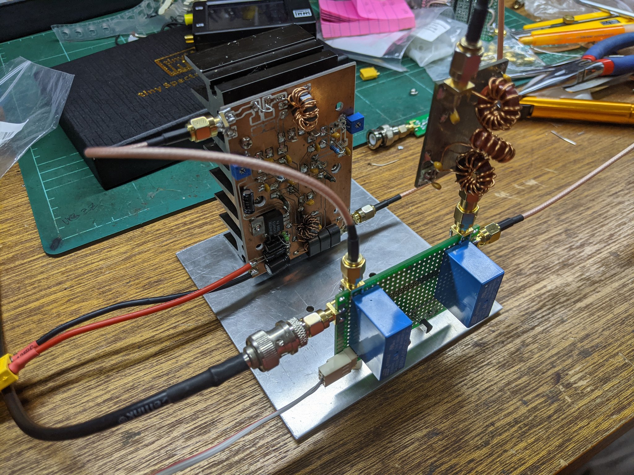
Now let’s make a proper version this time
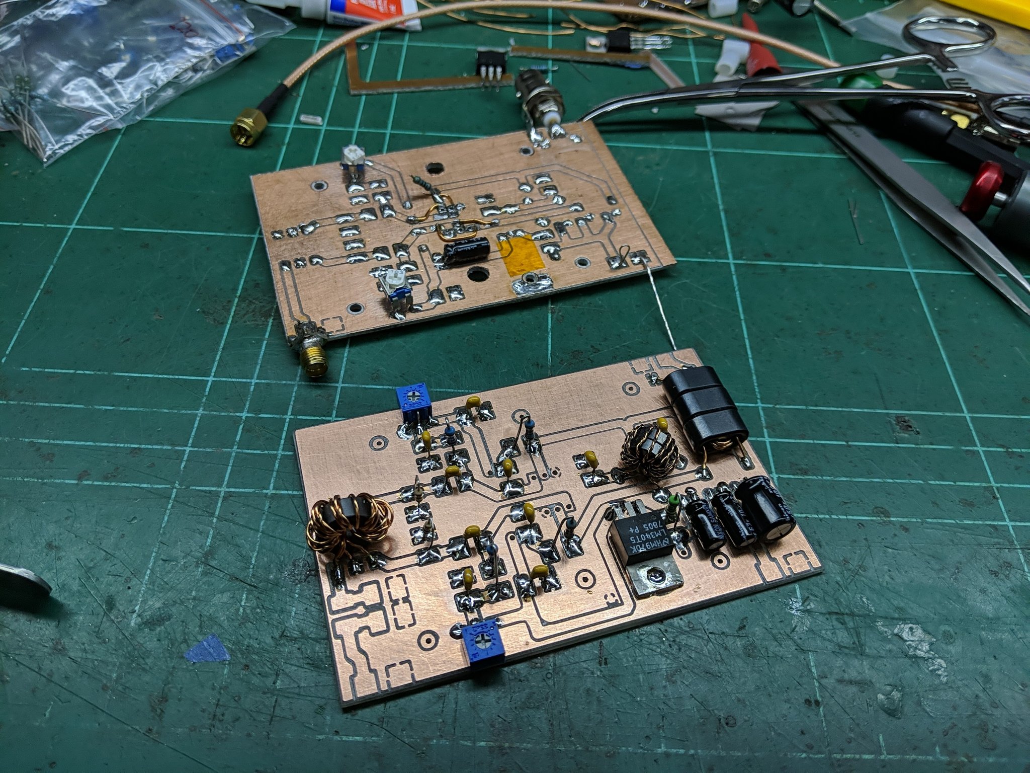
A new layout was made, a new board was milled on the CNC and the components transferred across to the new board
Worked perfectly. Pushing the input power up to 30V @ 3A the amp will easily get to 50W into 50 ohms, but I limit the supply to 28V and that seems to keep it around 45W output.
Time for an TX/RX switcher
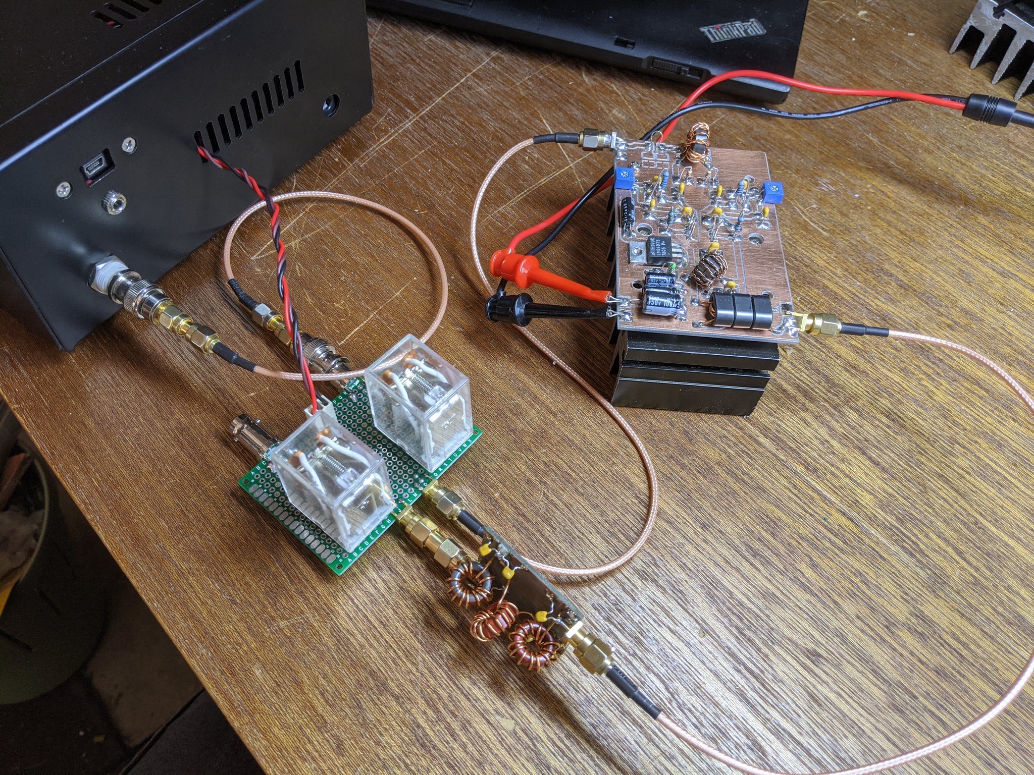
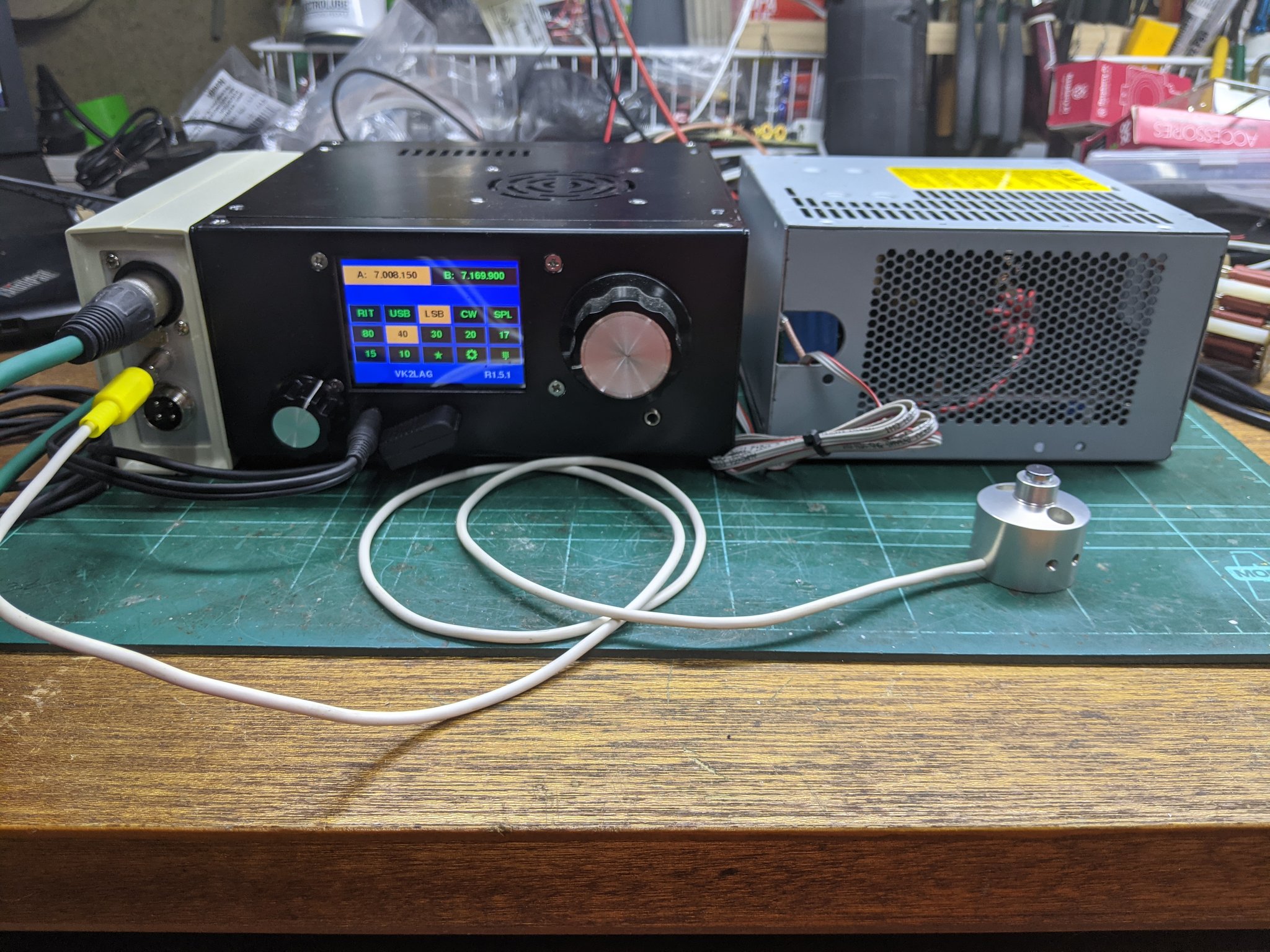
I needed a way to interface the linear with the uBitX. I pulled 12V from the TX/RX relay inside the uBitX and brought it outside to control a relay block I made for the linear. I really should just create a TX sensor on the input of the linear and have it handle the switching itself (future project) but for now this works.
Put it in a box!
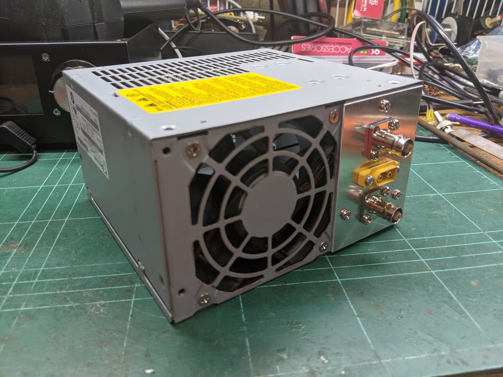
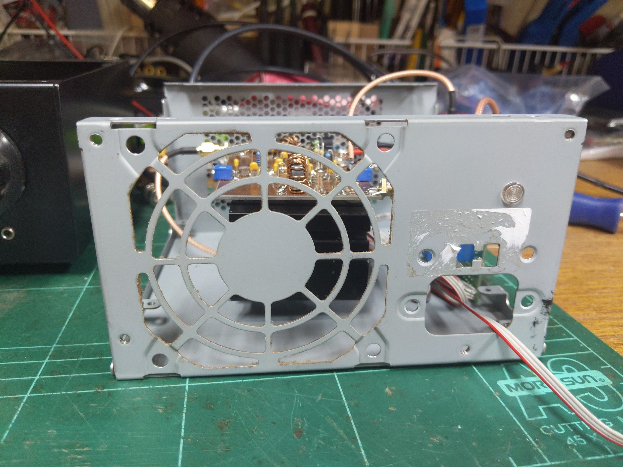
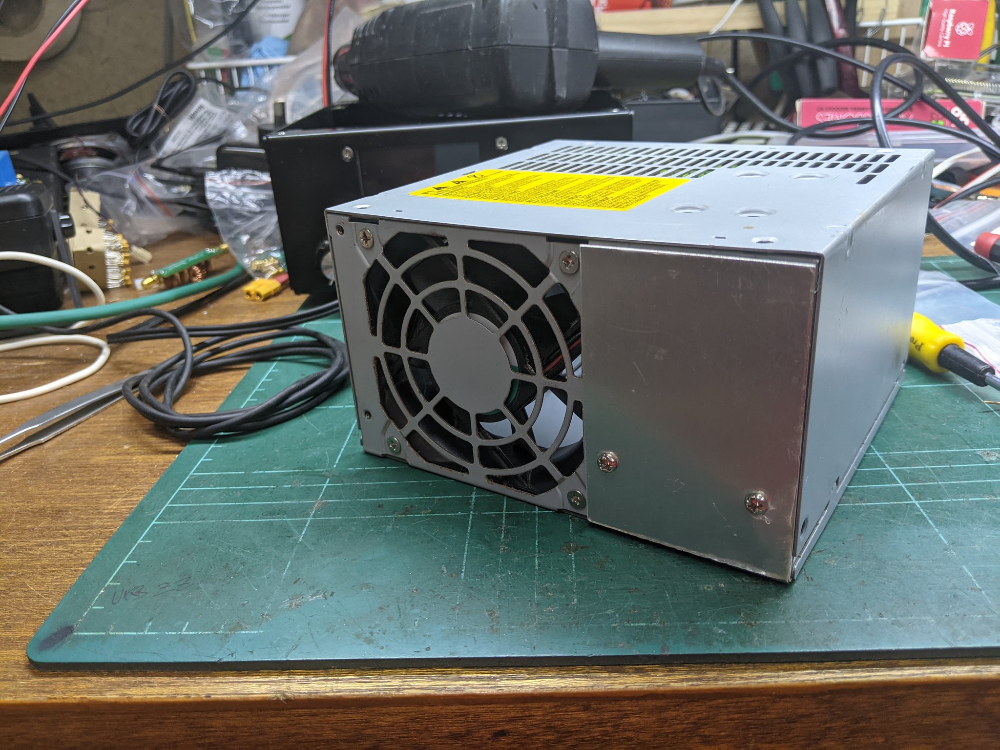
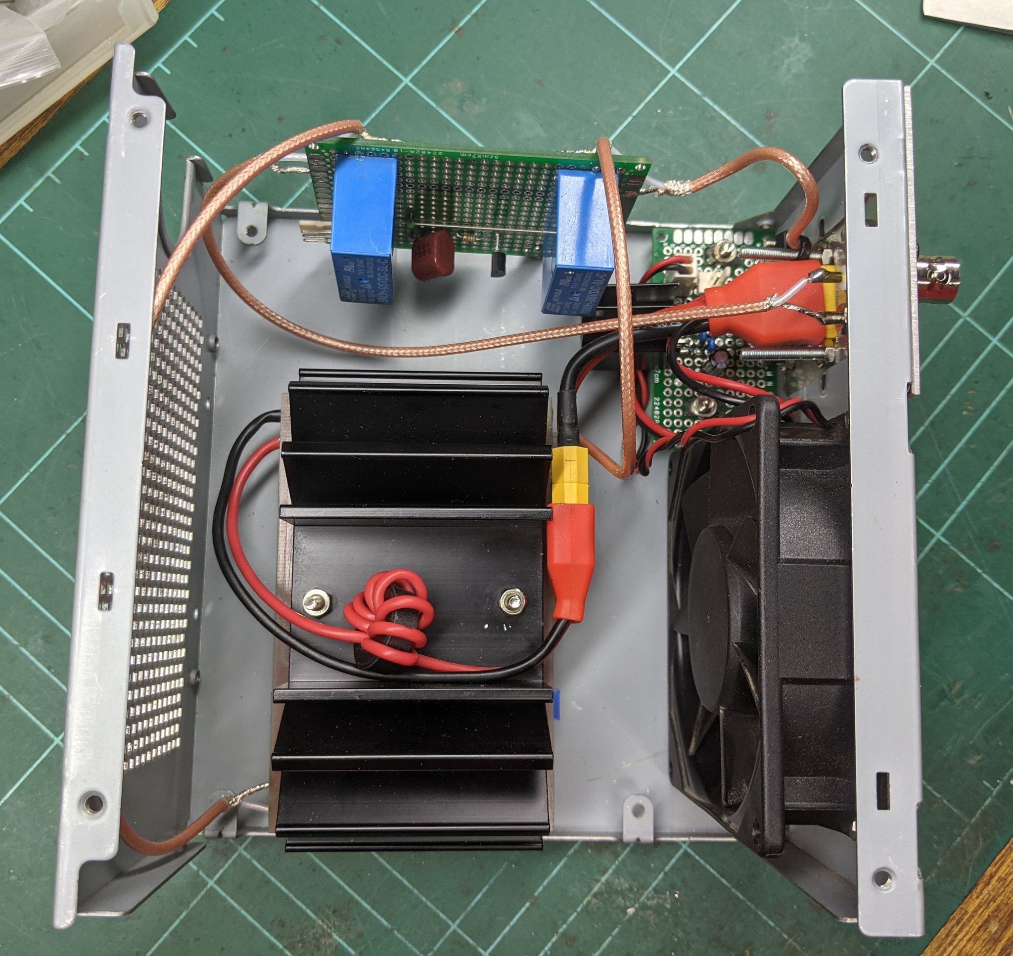
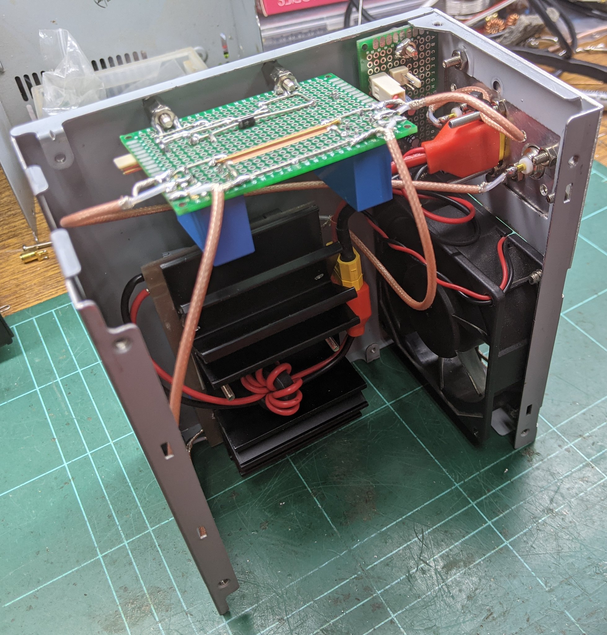
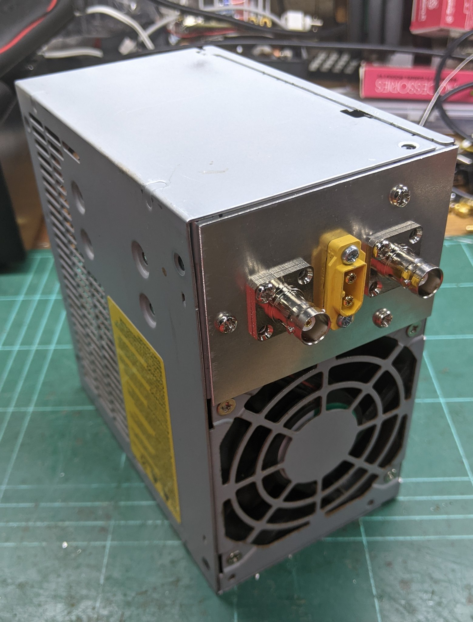
An old ATX PSU steel case was used to house the amplifier. It was handy because it had a 80mm fan already in the box and it was steel, so provided good shielding. Not much to look at though.
So, how’s it going?
After using it on air for a while and having finally breaking through the noise I have had many successful QSOs from all over Australia, NZ and the USA.
Suffice to say I’m really very very happy with it.