
So, for this post I want to talk about my development environment and where I’m up to as far as the Retro Challenge.
I’ve had a lot of issues with this project. Initially I was cruising well and looking well on track to make something really cool, but then I damaged the board.
The board started to exhibit a fault with it’s ability to load bytes from ROM. This became apparent as I started porting the TS2 ROM Monitor. When the fault occurred I started to gradually break the application down to the point of just the minimal initialization stuff for the CPU and UART and printing a string from ROM to the UART.
As I was doing this testing, the CPU would appear to crash or not properly enter into any exception handler (even when forced too by using an illegal instruction!). After many, many days of trial and error and screaming at the board I finally broke it down to the point of it was either a faulty CPU or I’m a complete idiot and can’t write five m68k assembly instructions.
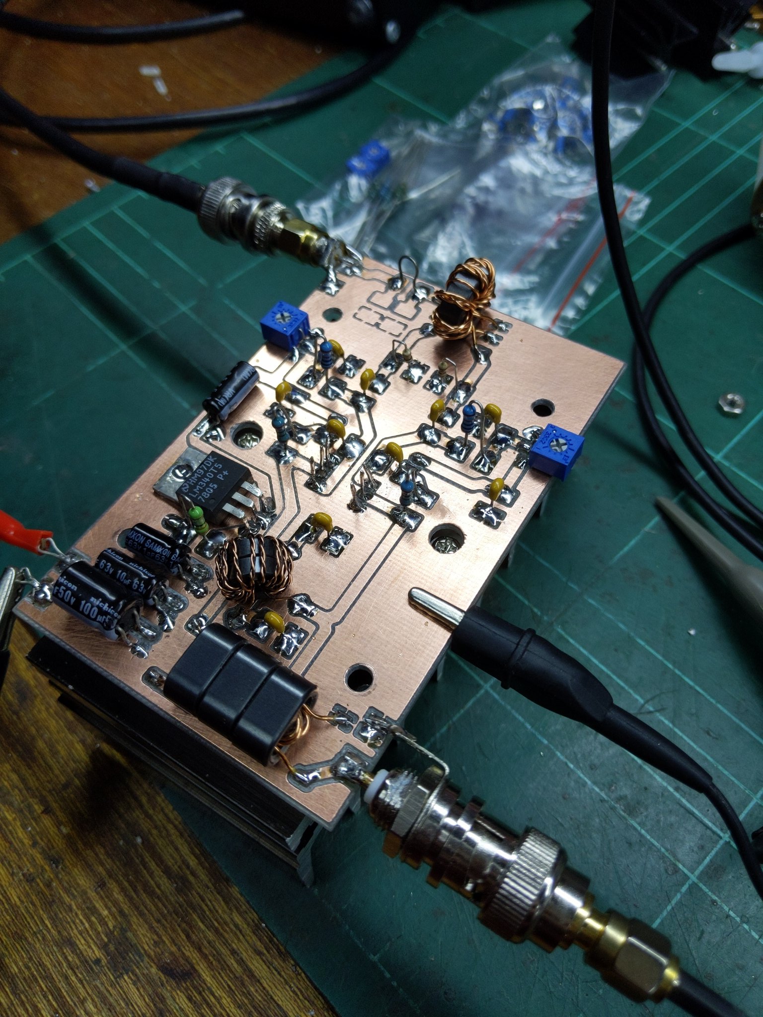
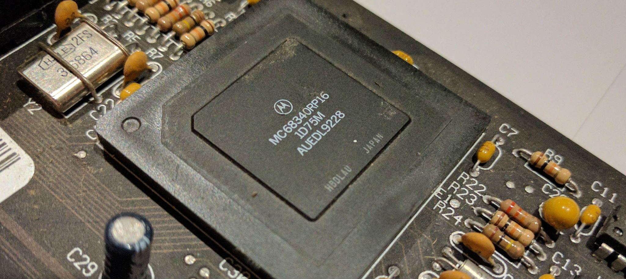
So, I cut my losses and switch to my fall back board that was a little newer and based on a MC68340 CPU. My main hesitation initially for not using this board to begin with was that it was a peripheral integrated CPU, which meant the board was basically ROM, RAM, CPU, and power related parts.
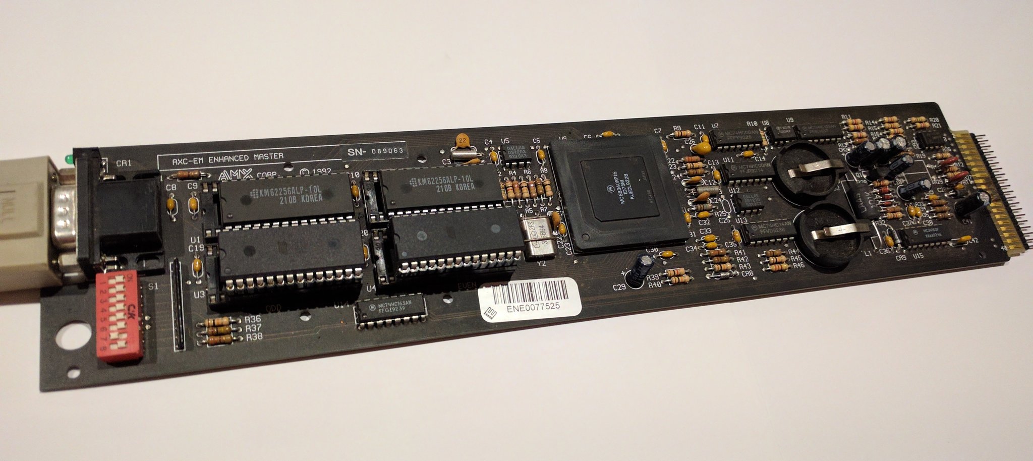
As it stands I’ve had a much more enjoyable time working with this board and so have progressed much further with the software, rather than staring at a blinking LED and hoping it blinks just right this time (if you follow me on Twitter you’ll know what I mean)..
The Software Environment.
At the moment I’m writing everything in assembler for the m68k. I’m on a Macbook Pro and I run the m68k development environment in a Ubuntu Xenial VM using Vagrant. Rather than trying to setup the cross compiler in OSX, I just opted to use Linux and the Ubuntu m86k deb packages.
So, to edit the code I use a Vagrant share and access the files in OSX using Vim in iTerm, and in another panel I have an open SSH session into the VM to do the compilation.
To get the code onto the EEPROMs I use a TL866a MiniPro programmer, which I’ve compiled the open source command line tool for it in OSX. This means to program the EEPROMs I run the commands in OSX.
Sounds difficult but it’s really not. I have a Makefile which handles all the compiling and ROM images, plus outputting dump files. It also has the recipe for programming the even and odd ROM images to the EEPROMs via the MiniPro tool.
The flow sorta looks like this:
- Makes changes to the source code in vim inside one iTerm pane.
- Switch to the VM pane that’s SSH’d into the VM. Run the make compile command.
- Switch back to the editor pane in iTerm.
- Put the even EEPROM in the programmer.
- From inside vim run the make commands to program the even EEPROM
- Rinse repeat for the odd ROM
Here is the Makefile I’m using, you can see it here on Github too.
M68K=m68k-linux-gnu
AS=$(M68K)-as
LD=$(M68K)-ld
COPY=$(M68K)-objcopy
DUMP=$(M68K)-objdump

ASFLAGS=-m68340 --warn --fatal-warnings
LDFLAGS=-T m68k.ld
DUMPFLAGS=-m68020 -x -D

EEPROM=AT28C256
PREFIX=m68k-

FMT=binary

SRCS=loader.s
OBJS=$(SRCS:.s=.o)
MAIN=loader

.PHONY: dump clean

all:	$(MAIN)

.s.o:
	$(AS) $(ASFLAGS) -o $@ $<

$(MAIN): $(OBJS)
	$(LD) $(LDFLAGS) -o $(MAIN).a $(OBJS)
	$(COPY) -b 0 -i 2 --interleave-width=1 -O $(FMT) $(MAIN).a $(PREFIX)$(MAIN)-even.bin
	$(COPY) -b 1 -i 2 --interleave-width=1 -O $(FMT) $(MAIN).a $(PREFIX)$(MAIN)-odd.bin

clean:
	rm -f *.o $(PREFIX)$(MAIN)-even.bin $(PREFIX)$(MAIN)-odd.bin $(PREFIX)$(MAIN).bin $(MAIN).a

prog_even:
	@echo Programming $(MAIN)-even onto $(EEPROM)
	minipro -p "$(EEPROM)" -w $(PREFIX)$(MAIN)-even.bin -s

prog_odd:
	@echo Programming $(MAIN)-odd onto $(EEPROM)
	minipro -p "$(EEPROM)" -w $(PREFIX)$(MAIN)-odd.bin -s

dump:	$(MAIN)
	$(DUMP) $(DUMPFLAGS) $(MAIN).a
Compilation and Linking
As you can see from the Makefile above I’m using m68k-linux-gnu-as to
assemble the object files from the source files. I am then using
m68k-linux-gnu-ld to link the object file(s) into the .a archive object
file. Which is then split into the even and odd ROM binary images needed
for the two 8 bit EEPROMS to make the 16bit wide program data.
I have a small linker script to handle the vector mapping, the stack and RAM locations etc. This step makes moving the resources around very easy, which I’m now thankful for because the two boards I have are vastly different in memory map to each other.
MEMORY
{
    ROM (rx) : ORIGIN = 0x00000000, LENGTH = 0x10000
    RAM (xrw) : ORIGIN = 0x00040000, LENGTH = 0x10000
}

/* stack location */
stack_size = 1024;

_stack_start = ORIGIN(RAM)+LENGTH(RAM)-0x10;
_stack_end = _stack_start - stack_size;

/* ram location */
_ram_start = ORIGIN(RAM);
_ram_end = ORIGIN(RAM)+LENGTH(RAM);

/* system integration module */
_sim40 = 0x80000;
_timers = _sim40 + 0x600;
_uarts = _sim40 + 0x700;
_dma = _sim40 + 0x780;

SECTIONS {
  .vectors 0x00 :
  {
    . = ALIGN(4);
    KEEP(*(.vectors))
    . = ALIGN(4);
  } > ROM

  .text 0x400 : {
    . = ALIGN(4);
    *(.text)
    . = ALIGN(4);
  } > ROM

  .data : { *(.data) } > RAM
  .bss :  { *(.bss)  *(COMMON) } > RAM
}

OUTPUT_ARCH(m68k)
I’ve been trying to get an .rodata section working, but for whatever reason
my sections end up with the wrong alignment and any strings I put there are in
the ROM image, but don’t appear to work. Maybe when I get some times I’ll
figure out why that is, for now I’m happy to just put the strings at the end of
the .text section.
Initializing the MC68340 CPU
The MC68430 is a great CPU, it has a lovely set of peripherals, and some very nice features. However getting it going can be a little trick as both the RAM and ROM positions are controlled completely by the System Integration Module. The “SIM40” is a peripheral module in the MC68340 that basically handles all the address decoding and glue logic the other board had in 74 series ICs. This allows cool things like loading the START and SP registers from the ROM, and then moving the ROM up high in the memory map and replacing where the ROM would be with RAM. All with just a few instructions. Done in hardware you’d need complex gating or a GAL to achieve something similar.
So to start with here is a chunk of code that configures the ROM and RAM locations in the memory map, and configures the CPU speed and interrupt maps.
*************************************************************************
*
*  Init the CPU and System Integration Module - Configs module options
*
.init:
            move.w      #0x2700, %sr                    | mask interrupts and set supervisor mode

            moveq       #7, %d0
            movec       %d0, %dfc
            move.l      #_sim40 + 1, %d0
            moves.l     %d0, 0x3ff00                    | move sim40 base address to 0x80000

            /* setup ROM chip select CS0 */
            move.l      #0x03fffd, _sm_csam0 + _sim40   | 16 bit port, three wait, mask FC bits, 256KB in size
            move.l      #0x000001, _sm_csbar0 + _sim40  | starting at 0x00000

            /* setup RAM chip select CS1 */
            move.l      #0x03fff1, _sm_csam1 + _sim40   | 16 bit port, zero wait, mask FC bits, 256KB in size
            move.l      #0x040001, _sm_csbar1 + _sim40  | starting at 0x40000

            /* setup system protects and clock */
            move.b      #0x06, _sm_sypcr + _sim40       | turn off watchdogs, bus fault, bus monitor
            move.w      #0x7c00, _sm_syncr + _sim40     | set clock to 15.991 MHz
            move.w      #0x420f, _sm_mcr + _sim40       | set MCR, no interrupts etc
In this project I’ve just kept the memory map really simple.
- 0x000000 is ROM
- 0x040000 is RAM
- 0x080000 is the SIM40 peripherals
I may switch the RAM and ROM around later as this would allow me to dynamically change the interrupt and trap vectors. Otherwise I have to hard code jumps to RAM locations inside the ROM where the vectors are in order to make them dynamic. At the moment I’m not really using interrupts, but I can see myself wanting too in the near future (also breakpoints etc in my ROM Monitor).
Initializing the MC68340
The MC68340 has a great suite of peripherals, from UARTs, Timers, System protection devices and DMA.
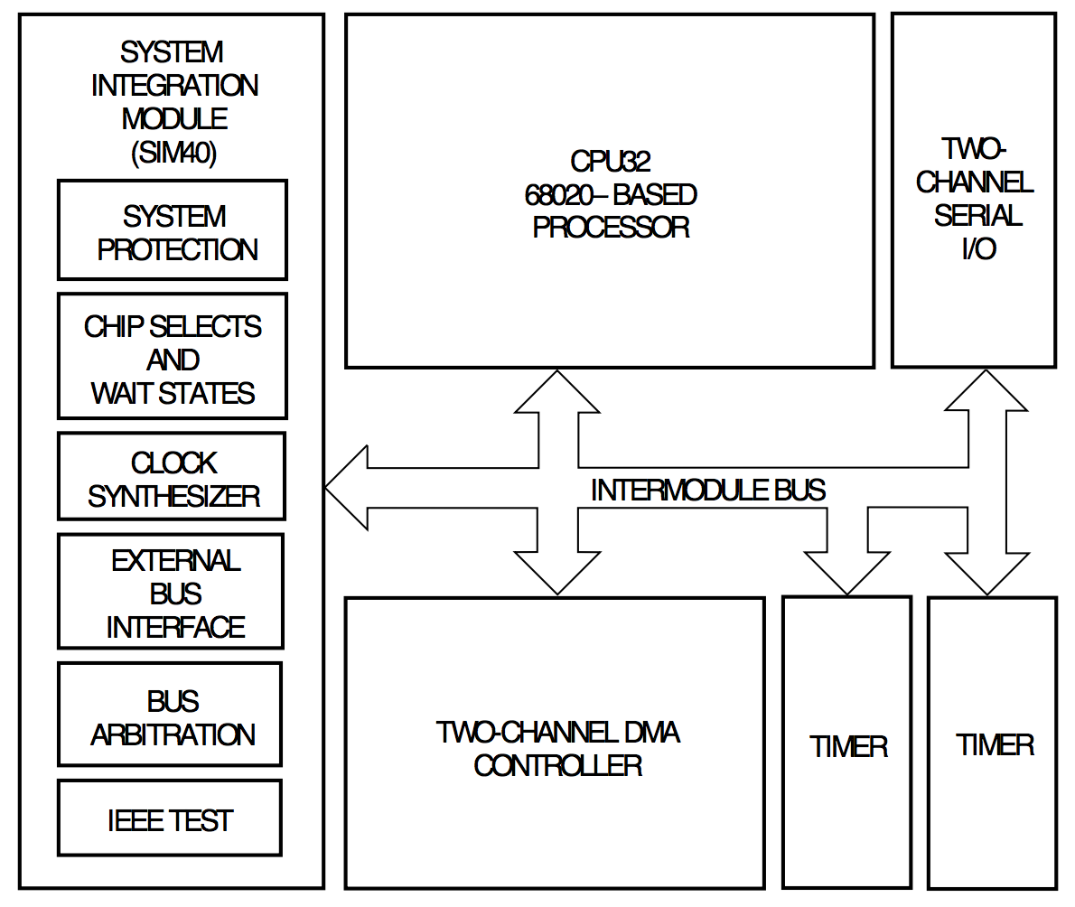
The SIM40 modules can move the addresses of these devices where ever you choose, but the layout is:
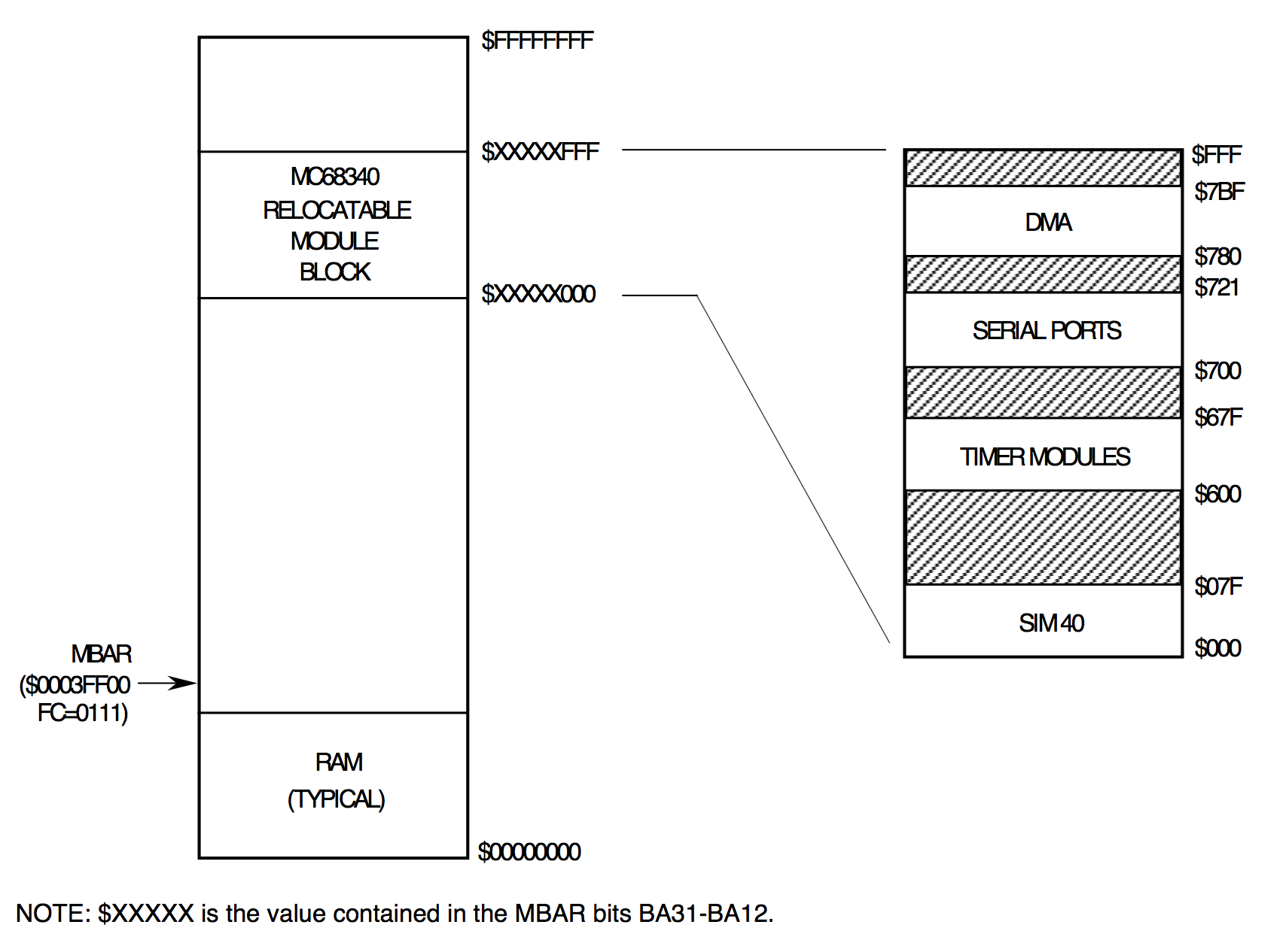
As you can see in the code above I’ve set it to the address of 0x080000. For
this project at the moment I’m turning more stuff off than I’m turning on.
By default all these peripherals are available and running, you have to disable
them if you’re not using them. Realistically this is more about power reduction
than anything, but like unused logic gates, I feel they must be put into a
known state. :)
So I turn off all watchdogs, and system protection peripherals (eg. double bus fault monitors, bus monitors, reset etc), the timers, and the DMA. Since I need a UART I configure one and disable the other.
The boot-loader
Initially I was just going to port across an existing ROM monitor for the m68k, there are plenty of quality ones out there but given the time I lost on the faulty CPU/board I quickly realized I won’t be able to port the monitor quickly enough if I had to burn EEPROMs each time to make any actual application with the board. I set out to make an Mandelbrot set with this board, so debugging a monitor wasn’t something I had time to do.
So speaking to my friend @trc_wm he suggested getting just something dumb that dumps binary into RAM and jumps to it, then write some python to push the binary at the serial port.
I started implementing that until I saw a few pieces of code that would load
srec format into RAM. I decoded the logic and wrote my own implementation in
a few hours, I figured this would be all round simpler in the long run as I
wouldn’t need to write the python. Instead I could just cut and paste the srec
records straight into the terminal, or at the very least cat them out to the
serial port.
Here is an example showing altering the code, compiling, copying the srecord data and running it:
Enough for today
That ought to do me for today. To achieve my goal of generating a Mandelbrot set with the board for the Retro Challenge, I’m going to work on either getting compiling C to run on the m68k, or port a BASIC/FORTH tomorrow and then write a Mandelbrot set generator in the chosen language.
We’ll see…

Comments